Wednesday, June 22, 2011
Almost there
Sorry for the lack of updates, my old Dell decided to pack it in. My friend Scott loaned me his old Dell and I did some troubleshooting. Thank goodness the hard drive still works, the power supply is OK, so I guess something crapped out on the motherboard. With the Cub this close I just don't want to waste the time shopping right now. The Cub is complete except for the breather tube and the front cowl pin bracket needed to be modified . I finished most of that tonight and I hope to have it running tomorrow. Sorry no pictures, not going to waste the time to sync my camera to this 2002 Dell !
Wednesday, June 15, 2011
Magnetos
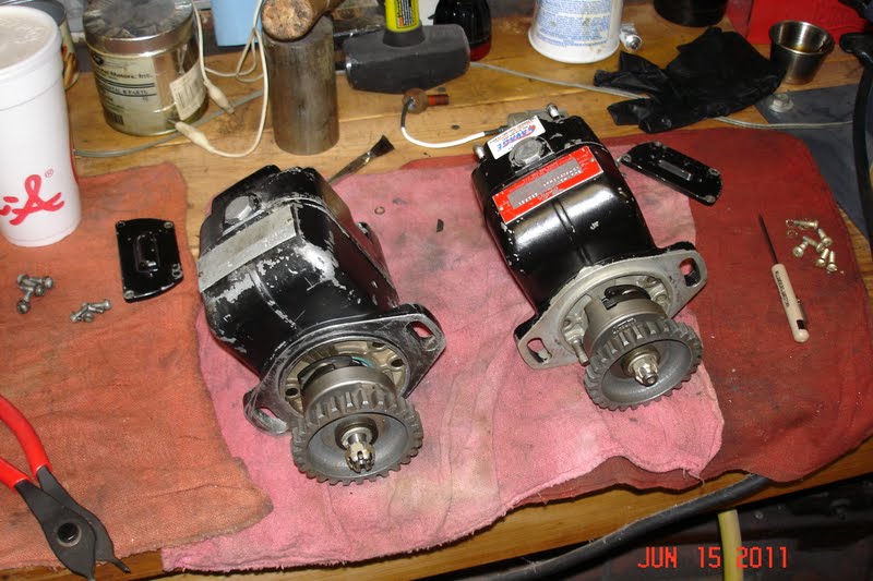
I thought I had two fresh overhaul magnetos to install however I was wrong. The project came with two magnetos that had Savage Magneto stickers on them and they looked great. I decided to disassemble these for inspection and fresh grease, that's when things went downhill. The first mag had a damaged drive end bearing race and a worn out front case. The second was not as bad but had an obsolete distributor installed. Here they are disassembled.
 Yes , I think I can get these back together.
 I ended up disassembling two more magneto cores I had in stock to get enough parts to build two good mags.Here is a shot of the drive end bearing race, looks like it might have been assembled with too much bearing pre-load? This requires a special bearing puller that I do not have(yet).
 The two Savage mags did have updated impulse couplings(snap ring style) That is a real plus.
 This operation really took some time because I had to constantly review the manual. Would have been an easy job if I did it everyday. I still need to replace one drive seal and the part will not be here until Monday. I did manage to get them put back together.
 The mag on the left is an old 51360-1 , looks a little rough but is in great shape inside. I will probably exchange the other two mags for Kelly Aerospace rebuilds, then keep these for spares. Sure does not look like 3 days work, well 1/2 days, it's yard work season.


Sunday, June 12, 2011
In with the new
After the thunderstorms last night it was a beautiful morning today. The help showed up at 9 as arranged and we loaded the engine in the truck.
 We just removed the bolts and laid it over onto Lynda's old seat cushion upside down.
Here it is ready to leave the shade tree engine shop.
 At the airport we put it right on the engine hoist. Here is the moving crew, JD , Scott , and you can see Buzz's foot.
 So I had to take another picture.
 I had everything ready so we hung the engine on the airframe. The sun beats in the hanger door in the morning so we knocked of till the afternoon. We got the engine mounted and the mount bolts torqued.


 The wire you see coming out of the cabin heat box at the far right is for my JPI digital tachometer. It has a pickup that screws into the magneto vent location and counts magnetic pulses. I will use this to back up the mechanical tach for the test flights. It runs on a 9 volt battery.


Here it is ready to leave the shade tree engine shop.


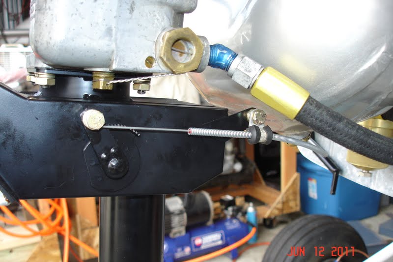
After a couple hours I went back out and started hooking up systems. I finished the throttle and it works really smooth with the new rodend bearing. I may look for a slightly smaller safety washer but this one works fine.

I had to put some chafe protection where the throttle rubs on the bottom of the oil screen. This is a common problem area on Cubs. This shot is a little blurry but you can get the idea.

After this I completed the oil pressure line and installed the tachometer drive.

Then I completed the fuel system, the fuel line could have been an inch longer but this will be OK for now. With the fuel on no leaks noted.

I installed the primer line and this completes the fuel system.

You can see that I also installed the carburetor heat control. I will search tonight for an all metal clamp for this location, I do not like a rubber cushioned clamp here. This cable will probably have to be moved around to clear the exhaust so this is just temporary.
I also got the cotter pins in all the engine mount bolts and installed the Brackett Air Filter. I installed the eyebrows but they rub slightly on the rocker covers and will need to be modified. I marked them and will work on them tomorrow morning . It is supposed to cool off for the next 3 days, hope to get the exhaust and cowling fitted.
Saturday, June 11, 2011
Out with the old
Today I cleaned up a few last details on the engine before it goes to the airport. I installed the inter-cylinder baffles , fuel fitting, primer fitting, and oil pressure line. The help is scheduled to show up Sunday at 9 to load the engine in the truck for the trip out to the airport. This afternoon I went out and removed the fit up engine and completed a few details on the airframe. Everything is ready for the installation tomorrow.

 Weather permitting the flight engine should be installed tomorrow.


Friday, June 10, 2011
Perseverance
Last night I baked the lifter covers in the oven and they were ready to install this morning. Since my lifters have the snap rings installed, I ground out some of the tab in the replacement covers. I did this free hand with a 5/8 inch carbide burr, so they are not all even.
 Here is a shot of the inside, should be no interference now.
 I installed these on the crankcase and I was back to the point where we started on Wednesday at 9 AM!!
 My friend Scott showed up at 9 and we installed and torqued the cylinders. With all the practice we had that complete by 10. The rest of the day was spent installing the intake system and cleaning up a bunch of details.
Here are some shots I took at the end of the day.

 If your wondering about the carburetor , I plan to build up another when I find my tub full of Strombergs. I want to see how this runs with the 44 main jet and the 55 main air bleed. It ran great on my Champ , but they can be finicky sometimes.
 The engine is ready to go to the airport tomorrow, if I can find two helpers without bad backs. In the morning I will load up all the tools and hardware for the trip out to the hanger. The oversize pushrods will not be available until next week so I have some time to finish the installation. Should be running late next week or the week after for sure.


Here are some shots I took at the end of the day.


Thursday, June 9, 2011
Revelation
Started today by removing the #1 cylinder to try and determine just what I had done wrong. After removing the lifter cover it all became obvious. Check out these pictures.
 The top cover was on the engine, the bottom one is a spare. Notice the design change. The upper lifter cover has two tabs per hole while the older lower one only has one outer tab. Here is a shot of the inside.
 This must have been a design change to correct the deficiency that I mentioned yesterday. The one outer tab did not prevent the lifter socket from coming out of the lifter body. Here is a picture of the outer end of the lifter body. Inside here is the hydraulic lifter and the socket that mates with the pushrod.
 With the engine assembled , if you pull out the pushrod for some reason(stuck valve) the lifter socket can come out and fall into the area inside the cover. The inside is the perfect size for the socket to fall in sideways and the next time you turn the propeller it bends and cracks (it's cast) the end of the tappet body. The only way to fix this is to completely disassemble the engine. You will only do this once, it is a painful lesson. I guess the two tabs are an attempt to correct this problem. These are Superior lifters and they have a snap ring groove you can just see. The snap ring prevents the socket from coming out of the body. The parts manual shows this snap ring , but I guess that Continental cheaped out for awhile and eliminated the snap ring groove and hence the problem. To fix my problem of the pushrod rubbing I decided to remove all the new style covers and install the older style covers. I went through my spares and selected 4 I liked. After a trip through the solvent tank, a few glass beads, alkaline wash, acid etch, and some alodine they were ready to paint.
 You can see that I also prepared the inter cylinder baffles. Since it was 95 degrees, I'm painting in the shade tree paint booth today. I am lucky to have college students for neighbors and not some Weiner! I have been running a paint test on the Stits epoxy primer and the Aerothane. When I primed the cowl back on May 19th I put the remaining primer in the freezer. I shot the Aerothane on May 22 and did the same. When I took it out today the Aerothane had cured into a rubber hockey puck.

However the epoxy primer had settled and needed to be mixed but was still in useable condition.
 This is sweet, I can mix up a batch of paint and when I need to paint just a few parts it is all ready to go after it warms up. When I shot the primer I could not detect any difference it the way it went on or cured. Here are the parts all primed.
 I let all these cure while I had dinner and then I went out and shot the Continental gold engine enamel . I know this was a lot of work but the rest of the engine got this treatment so I just could not half ass these. They came out nice.
 After I remove the tape I will bake these in the oven for a little while.
 Tomorrow, Scott is coming by at 9 and we will install the cylinders before it gets too hot. Personally, I will take too hot over too cold any day, water and air-conditioning are cheap compared to heating. I'm just glad I don't have a fur coat. The Bobcat did not get far from the water today.


However the epoxy primer had settled and needed to be mixed but was still in useable condition.


Wednesday, June 8, 2011
Aggravation
The day started out great, Scott came by at 9 and I had everything ready to assemble the cylinders. We had all 4 installed and torqued by 10:30. It is finally starting to look like an engine.
 We then set about measuring the cold tappet clearance so I could order oversize pushrods if required. The manual limits are 0.030-0.110, I did not have one within limits mine ranged from 0.117 to 0.161. I figured I needed 3 pushrods +0.030 and 5 at +0.070. I had a plastic tub full of pushrods so I set up this rig to measure them.
 It was surprising how close they all were to the same length.

I had one + 0.030 and one +0.070 pushrod in stock so I installed these on each cylinder just to make sure I could get them all within limits. This is where things started to unravel. I noticed some unusual binding when the oversize pushrods were installed in some cylinders. Notice anything in this picture?
 The original Continental pushrod is on the left, the Superior +30 pushrod is on the right. Notice that the Superior one is slightly larger diameter at 0.440 opposed to 0.378 for the original. The problem occurs in here.
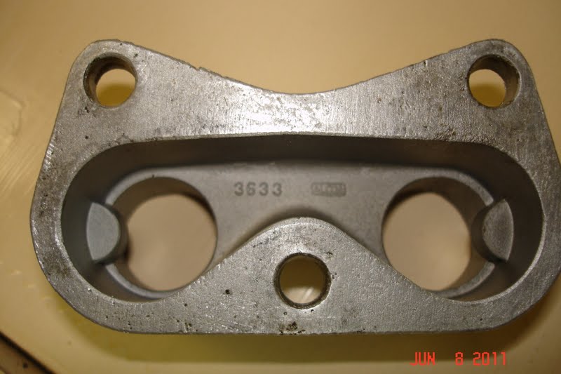
 Here is one of these castings removed from the engine.
 Notice the small tabs cast into the two holes. These are supposed to prevent the lifter sockets from being able to come out of the top of the lifter body. Anybody that has had that happen knows that these do not work as designed. Here is the other side.
 The problem is that these tabs contact the larger diameter pushrods just slightly causing an alignment problem 12 inches farther up where the pushrod contacts the rocker arm. I had noticed this wear once before on the C-90 on my Trojan but never put 2 and 2 together. I called the expert, Don, and they grind this tab down a little before assembly.
This all means that tomorrow I will get one more chance to get into Andie MacDowell's pant's as I live today all over again. The cylinders will come off, these covers get modified and it all goes back together. Not sure it will all get done tomorrow since the temperature is supposed to break the century mark tomorrow. Helpers are hard to find when it gets that hot, and I can't install the cylinders without help.


I had one + 0.030 and one +0.070 pushrod in stock so I installed these on each cylinder just to make sure I could get them all within limits. This is where things started to unravel. I noticed some unusual binding when the oversize pushrods were installed in some cylinders. Notice anything in this picture?


This all means that tomorrow I will get one more chance to get into Andie MacDowell's pant's as I live today all over again. The cylinders will come off, these covers get modified and it all goes back together. Not sure it will all get done tomorrow since the temperature is supposed to break the century mark tomorrow. Helpers are hard to find when it gets that hot, and I can't install the cylinders without help.
Tuesday, June 7, 2011
More Carburetor
Since the painting is never done I started today by painting a few items I had forgotten. I then finished the assembly of the Stromberg carburetor, you can tell when your finished because the weight of the safety wire equals the weight of the carb.! There is no good way to hold the thing while you safety wire, I usually end up with it between my knees. I really need to make up a fixture to hold the sucker while I work on it. With that finished I assembled the carb. to the intake spider and installed the new carb. heat box.
 You can see the two heat strips I installed on the oil sump. The one I installed on the Trojan burned out(different brand) so I went with two this time.
 Right now the mixture control is safety wired to the full rich position. I will fly it a little to see if I need to install a cockpit control, this back suction type mixture is not really very effective anyway.
 I spent the rest of the afternoon getting the cylinders ready for installation. The UPS man brought my valve springs so they got installed. I removed the 0-200 P/N 625958 springs and installed the C-90 P/N 24030 springs. The 0-200 springs have a larger wire diameter and about 20 lbs more tension. My friend Scott is coming by tomorrow at 9 and the cylinders will be going on. Not sure how much will get done tomorrow because the temperature is supposed to hit 97. With any luck, I should have engine pictures tomorrow .


Carburetor
Today I started by working on the ignition harness. I had been given a nice Skytronics harness, however I came to realize that it would not fit the C-90 engine. It was made for an A-65 and one magneto fires the top plugs on one side and the bottom plugs on the other. On the C-90 the timing is split so one mag fires all the top plugs and the other the bottom. The harness that came with the project was a Slick and since I have all the repair tools, I just fixed it as necessary. It is ready for installation, sorry no pictures of this operation.
I then started on the carburetor. When this engine was on my blue Champ, it ran fantastic, so I decided to retain the existing carburetor. Since it had been sitting for a while I opened it up for inspection and cleaning. The Stromberg manual requires the float level to be set wet with 0.710 specific gravity fuel at 0.5 psi pressure. I made this rig to meet this requirement.
 It is 2 feet of 4 inch plastic pipe fitted with a end cap. I drilled a hole in the side and fitted the on/off valve. The hose runs over to the carb. fuel inlet. I calculated the fuel height by hand first at 19.49 inches for 0.5 psi, I then found this cool calculator online that made it real easy.
http://hyperphysics.phy-astr.gsu.edu/hbase/pflu.html#fp
When the test is complete I use a battery service bulb to remove the fuel from the float chamber. I can then adjust the shims under the needle seat and retest. Works really good without much mess. The only thing I don't like is the static charge that sometimes builds up on the plastic pipe. If you stick your arm down inside the pipe all the hairs on your arm stand up ! I've been looking for some cheap aluminum pipe but have not found it yet.
 I think I did this calculation correctly but I'm open for any corrections to my logic. I should finish the carburetor tomorrow morning. Right now my plan is to finish as much as possible before moving the engine to the airport. The heat is supposed to get really bad and it's much more comfortable to work in the garage.
I then started on the carburetor. When this engine was on my blue Champ, it ran fantastic, so I decided to retain the existing carburetor. Since it had been sitting for a while I opened it up for inspection and cleaning. The Stromberg manual requires the float level to be set wet with 0.710 specific gravity fuel at 0.5 psi pressure. I made this rig to meet this requirement.

http://hyperphysics.phy-astr.gsu.edu/hbase/pflu.html#fp
When the test is complete I use a battery service bulb to remove the fuel from the float chamber. I can then adjust the shims under the needle seat and retest. Works really good without much mess. The only thing I don't like is the static charge that sometimes builds up on the plastic pipe. If you stick your arm down inside the pipe all the hairs on your arm stand up ! I've been looking for some cheap aluminum pipe but have not found it yet.

Sunday, June 5, 2011

Saturday, June 4, 2011
More details
It never ceases to amaze me how the smallest project can snowball into an entire day's work. I started Thursday to complete the installation of the oil sump. First you have to install the oil suction tube. I had cleaned up the one that was in the engine however on close inspection , I did not like the look of the solder that holds the screen. That sent me searching for my plastic tub full of these. On comparison with the others it became clear that the screen had been poorly repaired because it was a 1/4 inch shorter than all the others.
 This also reduces the inlet area because two additional rows of holes are blocked.
 I doubt this would make any difference but since I had better ones I replaced it. So I clean up 3 possible candidates and select the best for installation. This tube is installed in the bottom of the accessory case and is sealed with a copper crush washer.

You will notice that the only way to torque this is with a crows foot wrench installed on the torque wrench. This sends me searching for the Part 43 that has the formula to correct the torque wrench reading for the additional moment arm. With the safety wire installed I attempt to fit the sump and it won't fit down flush on the flange?
First I thought that is why the tube was shorter, but that was not the problem. It turns out that when tightened to the specified torque one of the hex points was blocking the sump from fitting flush. After trying 3 different crush washers I ended up filing off the offending point a little. I tried grinding out the sump but got nervous about the wall thickness. I guess the 4 quart cub model sump is not made to fit the c-90 engine that normally has the larger 6 quart sump. Here is how I had to file it off.
 With the safety wire installed it was ready for the sump.
 You can really see the difference between the aluminum crankcase and the magnesium rear case. While a little rough in spots it still has a lot of useful life remaining. Finally the sump is installed.
 See that filler neck clamp bolt below the right engine mount? Notice there is not enough clearance to install the nut with the sump tightened down. So I have to loosen everything , pull it back, install the nut and then tighten the sump. Between the head scratching , hunting for stuff, and figuring the best path forward this consumed almost a whole day!
Friday I completed the cylinders for installation( except for the valve springs) They are clean and everything is measured and ready for assembly. Of course since they are new, everything was right on spec.
 Everything has this black manganese phosphate coating, supposed to help it break in properly.
 They are ready to install on Tuesday when the springs arrive.
 Today (Saturday) I spent the morning installing anti chafe tape on the upper cowling. Then went out to the airport after lunch and check fitted the cowl. I then completed the throttle installation with the new rod end bearing I got on Friday. I also completed the carb heat and the primer installation. The last item here is the magneto wires because I forgot to take out the terminals. The only possible holdups might be the cold tappet clearance (will have to order pushrods) and the ignition harness. With some luck and perseverance I might be flying next weekend!


You will notice that the only way to torque this is with a crows foot wrench installed on the torque wrench. This sends me searching for the Part 43 that has the formula to correct the torque wrench reading for the additional moment arm. With the safety wire installed I attempt to fit the sump and it won't fit down flush on the flange?
First I thought that is why the tube was shorter, but that was not the problem. It turns out that when tightened to the specified torque one of the hex points was blocking the sump from fitting flush. After trying 3 different crush washers I ended up filing off the offending point a little. I tried grinding out the sump but got nervous about the wall thickness. I guess the 4 quart cub model sump is not made to fit the c-90 engine that normally has the larger 6 quart sump. Here is how I had to file it off.


Friday I completed the cylinders for installation( except for the valve springs) They are clean and everything is measured and ready for assembly. Of course since they are new, everything was right on spec.


Subscribe to:
Posts (Atom)